
Enclosures as code: why I design 3D-printed parts in OpenSCAD
Parametric enclosures, tolerance variables and fit-check prints — how treating plastic like source code made my hardware iterations faster.
I spent a long time in infrastructure, where everything that matters is written down as configuration. So when I started designing enclosures, I gravitated to a CAD tool that works the same way: OpenSCAD, where a 3D part is a program.
That choice looks odd to people used to dragging shapes around in a GUI. Here's why it works for me.
My setup is deliberately ordinary: OpenSCAD on the laptop, STL out, and a consumer 3D printer (a FlashForge AD5X) on the bench. Nothing here needs an expensive machine — it needs a repeatable workflow.
The part is defined by its numbers
An enclosure for a PCB is mostly a set of relationships: the board is this big, the wall is this thick, the screen window lines up with the display, the USB opening lines up with the connector. In OpenSCAD those relationships are the design:
pcb      = [62, 48, 1.6];  // board size from KiCad
wall     = 2.2;
gap      = 0.35;           // clearance per side, tuned per printer
standoff = 4;

inner = [pcb.x + 2*gap, pcb.y + 2*gap];
outer = [inner.x + 2*wall, inner.y + 2*wall];

difference() {
    rounded_box(outer, h = 18, r = 4);
    translate([wall, wall, wall]) rounded_box(inner, h = 20, r = 2);
    usb_cutout(at = [outer.x/2, 0, wall + standoff]);
}
When the PCB changes size in the next revision, I change one line. Everything else — walls, cutouts, screw bosses — follows.
Tolerance is a variable, not a guess
Every printer and filament combination has its own personality. A hole designed at 3.0 mm might print at 2.8 mm. Instead of fixing each hole by hand, I keep a single gap value and a few named tolerances (press-fit, slip-fit, loose) that every feature uses.
The trick is to calibrate once with a test coupon: a small printed plate with pegs and holes at several clearances. Print it, test which ones fit how you want, and write those numbers into the file. Now every future part inherits that knowledge.
Print the fit, not the whole thing
A full enclosure can take hours to print. Most questions don't need the full part:
- Does the USB plug clear the opening? Print a 5 mm-tall slice of that wall.
- Does the board sit level on the standoffs? Print just the floor.
- Does the button cap travel freely? Print the cap and the hole, nothing else.
Because the model is code, making a "slice" is a one-line intersection() with a box. Ten-minute prints answer questions faster than five-hour ones.
Designing board and box together
The real payoff came when PCB and enclosure started evolving together. Board outline and mounting holes come out of KiCad; the enclosure reads those numbers; a printed shell shows whether a thumb can comfortably reach the screen. Sometimes the plastic tells you to move a component on the board — and finding that out from a cheap print is much better than finding it out after a fab order.
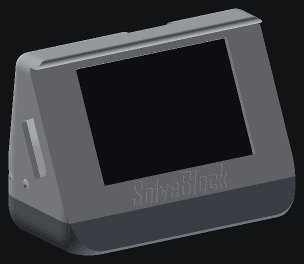
For SolveBlock that loop happened many times: placement, fit, ergonomics, assembly order. The best enclosure changes didn't come from the screen; they came from holding prints in my hand.
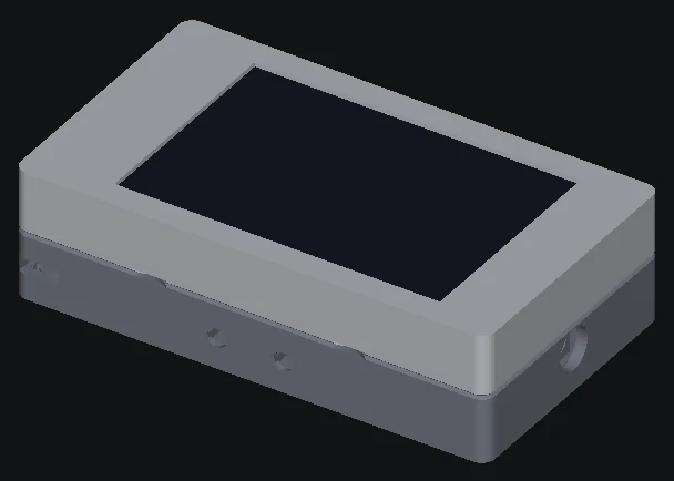
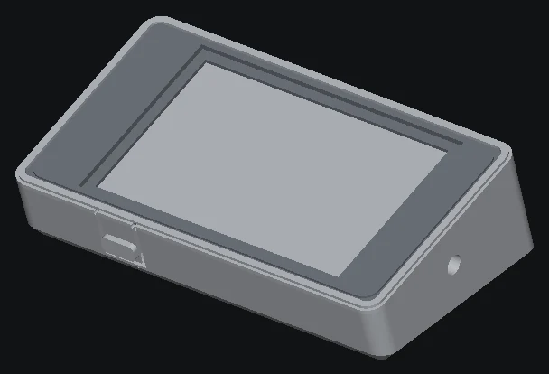
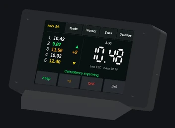
Those four SolveBlock shapes all came out of the same source file — changing the shape is a re-run, not a redraw.
Version control works on plastic too
Since the design is a text file, it lives in git beside the firmware. Every revision has a diff. "What changed between the shell that fit and the one that didn't?" is a git diff away. That alone is worth the learning curve.
Where OpenSCAD isn't great
It's honest to admit the limits: organic shapes, fillets on complex edges and anything sculpted are painful in OpenSCAD. For those, a traditional CAD tool wins. But for boxes, brackets, fixtures and jigs — the bread and butter of electronics projects — code-defined parts are fast, precise and repeatable.
Takeaways
- Put your dimensions and tolerances in named variables.
- Calibrate clearances once with a test coupon.
- Print small slices to answer specific fit questions.
- Keep enclosure source in git next to the firmware and PCB.
Plastic is just another kind of source code. Treat it that way and it'll iterate like software.
Some links in these notes are affiliate links. If you buy through one, I may earn a commission at no extra cost to you. I only link to tools I use or would recommend.